The idea in one sentence
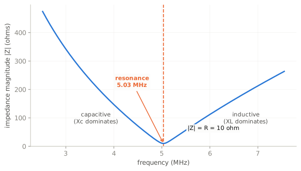
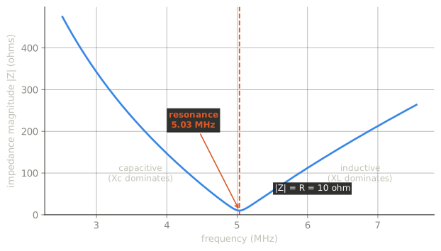
Inductive reactance rises with frequency; capacitive reactance falls with it. At exactly one frequency they are equal and opposite, they cancel, and the circuit looks purely resistive. That is resonance.
Everything tuned in radio — filters, traps, tuned circuits, resonant antennas — is this one idea wearing different clothes.
Series and parallel behave oppositely
This is the distinction exams test hardest, and it is worth getting straight once.
Series resonance: minimum impedance, maximum current. The two reactances cancel in the series total, leaving only the resistance. A series resonant circuit is a short at its resonant frequency and an obstacle everywhere else — which is what makes it a notch filter.
Parallel resonance: maximum impedance, minimum line current. The two reactances still cancel, but in a parallel arrangement the cancellation removes the paths for current. A parallel resonant circuit is an open at its resonant frequency — which is what makes it the tuned circuit in an oscillator or the trap in a multiband antenna.
Same cancellation, opposite consequence. If you remember only one thing: series shorts, parallel opens.
The reactances do not disappear
At resonance the two reactances cancel in the total. Individually they are still there and can be enormous.
In a high-Q series resonant circuit the voltage across the inductor, and across the capacitor, can be many times the applied voltage — equal and opposite, so they sum to nothing, while each is real enough to arc. This surprises people building antenna tuners and mobile loading coils, where the voltage at a coil end can be far higher than anything the transmitter produces.
From resonance to matching
Maximum power reaches a load when the load impedance equals the source impedance. A mismatch reflects part of the wave back toward the source instead of delivering it.
This is why everything in a station is nominally 50 ohms: transmitter output, feed line, and antenna at its resonant frequency. It is an arbitrary convention that everyone agreed on, and its value is precisely that everyone agreed.
A resonant antenna matters because resonance is how you get the reactance to zero. An antenna that is not resonant presents resistance plus reactance, and the reactance is what the feed line cannot deliver power into.
SWR: measuring the mismatch
Standing wave ratio is the ratio of maximum to minimum voltage along the feed line, caused by reflection from a mismatched load. A perfect match reads 1:1.
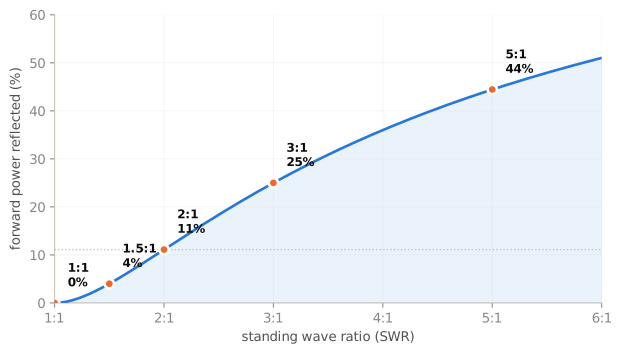
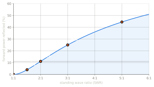
The arithmetic is worth carrying: reflected power is . So a 2:1 SWR sends about 11% of the power back — a through loss of roughly half a decibel, which is nothing you would hear.
That is why 2:1 is a working limit rather than a disaster. The real costs are elsewhere:
- The transmitter. A solid-state final amplifier reduces power or shuts down when it sees reflected power, so high SWR costs output long before it costs radiated signal.
- The feed line. Reflected power travels back down the line, is partly re-reflected, and traverses the loss again. In a lossy line at UHF, a mismatch multiplies an already significant loss.
The two things SWR does not tell you
SWR is a symptom, not a diagnosis. A high reading says the impedance at the far end is not 50 ohms. It does not say why — wrong length, bad connector, water in the coax, and a genuinely detuned antenna all read the same.
A good SWR does not mean a good antenna. A 50 ohm dummy load shows a perfect 1:1 and radiates almost nothing. So does a badly lossy feed line, because loss attenuates the reflection on its way back. A suspiciously perfect SWR on a long run of old coax is a warning, not a reassurance.
And an antenna tuner does not tune the antenna. It transforms the impedance the transmitter sees at the tuner. The standing wave between tuner and antenna is unchanged, and so is the loss it causes. A tuner makes the transmitter happy; it does not fix the antenna.
Check yourself
- At resonance in a series circuit, what happens to impedance and current?
- Your SWR reads 3:1. Roughly what fraction of your power comes back?
- Your feed line is old and lossy and your SWR reads a perfect 1:1. Is that good news?
Answers
- Impedance is at a minimum (equal to the resistance) and current at a maximum.
- — about 25%.
- Probably not. Line loss attenuates the reflected wave on its way back, so a lossy line flatters the SWR reading. Measure at the antenna end if you can.