Why coax, and why 50 ohms
Why is coaxial cable the most common feed line for amateur radio antenna systems?
It is easy to use and requires few special installation considerations.
Coax is shielded, so it can be run along metal, through walls, and beside other cables without picking up or radiating much. Open-wire line has lower loss and demands to be kept clear of everything — including you.
What is the most common impedance of coaxial cables used in amateur radio?
50 ohms.
Fifty is a compromise between the impedance of lowest loss and the impedance of highest power handling in air-dielectric coax. Its real value is that everyone agreed: radios, antennas, meters, and cables all assume it.
Loss
Three facts, in the order they matter.
Loss rises with frequency.
What happens as the frequency of a signal in coaxial cable is increased?
The loss increases.
A run of RG-58 that costs you a fraction of a decibel on 40 metres costs several decibels at 440 MHz. Feed-line choice barely matters on HF and matters enormously at UHF.
Thicker is better.
What is the electrical difference between RG-58 and RG-213 coaxial cable?
RG-213 cable has less loss at a given frequency.
Same 50 ohms, same job, bigger conductor and more dielectric. RG-58 is thin, flexible, cheap, and lossy; RG-213 is thick, stiff, and much better. For a UHF run of any length, use the thick one.
The lowest-loss line is air-insulated hardline — a rigid or semi-rigid cable with mostly air as the dielectric. Commercial installations use it; hams find surplus lengths of it and treasure them.
Sources of loss — the pool answers “all these choices are correct” — are conductor resistance, dielectric losses, and radiation from the line itself.
Connectors
PL-259 — the familiar silver barrel, sometimes called a UHF connector, which is a misnomer. They are commonly used at HF and VHF frequencies. The design is not a constant-impedance connector and it degrades above a few hundred megahertz.
Type N — the most suitable RF connector for frequencies above 400 MHz. Constant impedance, weatherproof when assembled properly, and the right choice for 70 centimetres and above.
Everything outdoors needs weather protection. The pool asks which connectors should be carefully taped when used outdoors and answers “all these choices are correct”. Water in a coaxial cable wicks along the braid, ruins the dielectric, and raises loss permanently. Sealing is not optional and it is not glamorous.
SWR
What is standing wave ratio (SWR)?
A measure of how well a load is matched to a transmission line.
Not a measure of how well the antenna radiates. Not a measure of how far you will get. A measure of match.
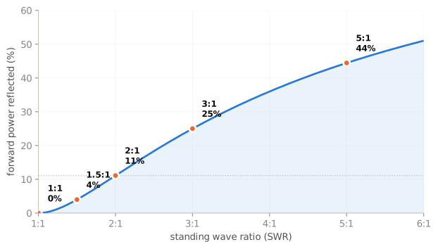
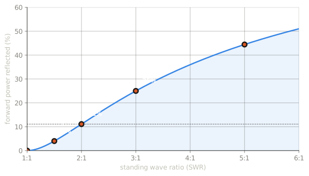
The number to carry: 2:1 sends about 11% of the power back, which is roughly half a decibel of through loss. That is why 2:1 is a working limit rather than a crisis. What actually suffers is the transmitter — a solid-state final folds back its power when it sees reflected energy — and a lossy feed line, where the reflected wave traverses the loss a second time.
Diagnosing with SWR
What can cause erratic changes in SWR?
Loose connection in the antenna or feed line
Erratic is the key word. A steady high SWR is a mismatch — wrong length, wrong antenna, wrong band. An SWR that jumps around as you move the coax, or changes with wind or rain, is a mechanical fault. Check connectors first; they fail more often than antennas do.
Two more readings worth interpreting:
- SWR that rises steadily over months usually means water ingress.
- SWR that looks suspiciously perfect on a long, old run may be line loss attenuating the reflection. A dead-flat 1:1 across an entire band is a warning, not a triumph.
Antenna tuners
What is the major function of an antenna tuner (antenna coupler)?
It matches the antenna system impedance to the transceiver’s output impedance.
Read what that does not say. It matches at the tuner. The standing wave between the tuner and the antenna is exactly what it was, and so is the loss it causes in the feed line.
A tuner makes the transmitter happy, which is genuinely useful — it stops the final folding back and lets you operate. It does not fix the antenna, it does not recover the loss, and calling it an “antenna tuner” has misled generations. “Transmatch” or “coupler” is the more honest name.
Choosing, in practice
| Situation | Choice |
|---|---|
| Short HF run | RG-58 is adequate |
| Any HF run over ~50 feet | RG-213 or better |
| VHF, any meaningful length | RG-213 minimum |
| UHF | the best line you can afford; length hurts |
| Above 400 MHz | Type N connectors |
| HF and VHF | PL-259 is fine |
| Anything outdoors | seal it properly |
Check yourself
- Your 70 cm SWR is fine but signals are weak both ways. What do you suspect?
- SWR jumps when you flex the coax at the antenna. Diagnosis?
- You add a tuner and SWR at the radio drops to 1:1. What has improved, and what has not?
Answers
- Feed-line loss — likely thin cable or a long run at UHF, possibly water ingress. A good SWR with poor performance is the classic signature of a lossy line.
- A loose connection in the antenna or feed line. Erratic SWR is mechanical.
- The transmitter now sees a matched load and will deliver full power. The mismatch beyond the tuner, and the feed-line loss it causes, are unchanged.