What sets a line’s impedance
Which of the following factors determine the characteristic impedance of a parallel conductor feed line?
The distance between the centers of the conductors and the radius of the conductors
Geometry and dielectric — nothing else. Not length, not frequency, not what is connected to either end. That is why a 50-ohm cable is 50 ohms whether you have three feet or three hundred.
Common values:
| Line | Impedance |
|---|---|
| Station coax | 50 ohms |
| Video and broadcast coax | 75 ohms |
| “Window line” (ladder line) | 450 ohms |
| Open-wire line | 300–600 ohms |
Computing SWR
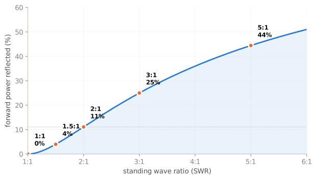
For a purely resistive load, divide the larger impedance by the smaller.
200-ohm resistive load on a 50-ohm line: 200 / 50 = 4:1.
10-ohm resistive load on a 50-ohm line: 50 / 10 = 5:1.
Note the second one carefully: the load is below the line impedance and the ratio still comes out greater than one, because you always divide larger by smaller. And a 250-ohm load would read the same 5:1 — SWR cannot tell you which side of 50 ohms you are on.
What causes reflected power at an antenna’s feed point?
A difference between feed line impedance and antenna feed point impedance.
What must be done to prevent standing waves on a feed line connected to an antenna?
The antenna feed point impedance must be matched to the characteristic impedance of the feed line.
The matching-network question
This is the one that separates people who understand SWR from people who have memorised it.
If the SWR on an antenna feed line is 5:1, and a matching network at the transmitter end of the feed line is adjusted to present a 1:1 SWR to the transmitter, what is the resulting SWR on the feed line?
5:1
Unchanged. The tuner transforms the impedance the transmitter sees. The standing wave between the tuner and the antenna is exactly what it was, and so is the loss that standing wave causes in the line.
A tuner makes the transmitter happy. It does not fix the antenna, does not reduce the standing wave beyond itself, and does not recover the loss.
Loss
In what units is RF feed line loss usually expressed?
Decibels per 100 feet.
How does the attenuation of coaxial cable change with increasing frequency?
Attenuation increases.
And the interaction that matters:
What is the relationship between high standing wave ratio (SWR) and transmission line loss?
High SWR increases loss in a lossy transmission line
Read the qualifier: in a lossy line. Reflected power travels back down the line, is partly re-reflected at the transmitter end, and traverses the loss again. In a nearly lossless line that costs almost nothing; in a long UHF run of thin coax it compounds badly.
This is why 2:1 is a non-event on 80 metres with good cable and a real problem on 70 centimetres with RG-58.
The reading that lies
What is the effect of transmission line loss on SWR measured at the input to the line?
Higher loss reduces SWR measured at the input to the line.
The reflected wave is attenuated on its way back, so less of it reaches your meter. A lossy line therefore improves the SWR you read while making everything worse.
The practical consequence: a suspiciously flat SWR across a whole band, on a long or old run of cable, is a warning rather than a triumph. Measure at the antenna end if you can, or compare a known-good short jumper against the installed run.
Check yourself
- A 300-ohm resistive load on 50-ohm coax. SWR?
- Your antenna shows 3:1 at the antenna. You add a tuner at the radio and read 1:1. What is the SWR on the feed line now?
- Your 200-foot UHF run reads a perfect 1:1 across the band. Good or bad sign?
Answers
- 300 / 50 = 6:1.
- 3:1. The tuner changes what the transmitter sees, not what is happening on the line.
- Suspicious. High loss attenuates the reflected wave and flatters the reading. Measure at the antenna end.