Two ways to write the same impedance
An impedance has two independent parts, so it needs two numbers. There are two conventional ways to supply them.
Rectangular: — a resistive part and a reactive part.
When using rectangular coordinates to graph the impedance of a circuit, what do the axes represent?
The X axis represents the resistive component, and the Y axis represents the reactive component.
Where is the impedance of a pure resistance plotted on rectangular coordinates?
On the horizontal axis.
Zero reactance means zero on the vertical axis, so a pure resistance sits on the horizontal axis.
Polar: magnitude and angle.
How are impedances described in polar coordinates?
By magnitude and phase angle.
What coordinate system is often used to display the phase angle of a circuit containing resistance, inductive, and/or capacitive reactance?
Polar coordinates
The j operator, and its sign
j marks the reactive part, and its sign says which kind:
- +j is inductive
- −j is capacitive
Which of the following represents pure capacitive reactance of 100 ohms in rectangular notation?
0 − j100.
No resistance, so the real part is zero; capacitive, so the sign is negative.
What does the impedance 50 − j25 ohms represent?
50 ohms resistance in series with 25 ohms capacitive reactance.
Read it straight off: 50 resistive, 25 capacitive.
Which of the following represents a pure inductive reactance in polar coordinates?
A positive 90 degree phase angle.
Pure reactance means no resistive part, so the impedance lies on the vertical axis — at +90° for inductive and −90° for capacitive.
Which form for which job
The two forms are equivalent, and each makes a different operation easy. Knowing which to use is the practical skill.
| Operation | Easier in |
|---|---|
| Adding impedances in series | rectangular — add real parts, add imaginary parts |
| Multiplying or dividing | polar — multiply magnitudes, add angles |
| Taking a reciprocal (impedance → admittance) | polar — reciprocal magnitude, negate angle |
| Reading off R and X | rectangular |
| Reading off magnitude and phase | polar |
That is why the admittance conversion in the previous lesson is stated in polar form: it is one step there and messy in rectangular.
Phasor diagrams
What kind of diagram is used to show the phase relationship between impedances at a given frequency?
Phasor diagram.
A phasor diagram plots each impedance as a vector — length for magnitude, angle for phase — so a series combination becomes vector addition you can see. It is the picture that makes “the reactances cancel at resonance” obvious: two vectors of equal length pointing exactly opposite.
At a given frequency matters. Reactance changes with frequency, so a phasor diagram is a snapshot.
Reading figure E5-1
Three pool questions ask you to locate an impedance on this figure.
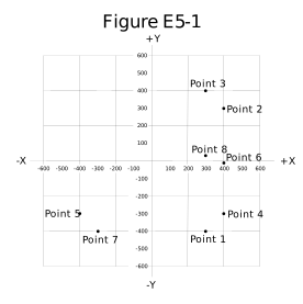
The method is mechanical:
- Compute the reactance at the stated frequency — X_L = 2πfL or X_C = 1/(2πfC).
- The resistance is the horizontal coordinate.
- The reactance is the vertical coordinate, positive up for inductive and negative down for capacitive.
- Find the point with roughly those coordinates.
Nothing more subtle than that. The arithmetic is the reactance formula from the General track; the figure just asks you to plot the answer.
Frequency response graphs
What type of Y-axis scale is most often used for graphs of circuit frequency response?
Logarithmic.
Because response spans orders of magnitude and because decibels are logarithmic. A filter with 60 dB of ultimate rejection has a stopband a millionth of its passband in power — invisible on a linear axis, clearly readable on a logarithmic one.
The mode-bandwidth figure in the Technician signals module makes the same point about the frequency axis.
Check yourself
- Write “30 ohms resistance in series with 40 ohms inductive reactance” in rectangular form. What is its magnitude?
- Where does 0 + j75 plot, and what is it?
- You need to add two series impedances. Which coordinate form?
Answers
- 30 + j40. Magnitude = √(30² + 40²) = 50 ohms.
- On the vertical axis, above the origin — a pure inductive reactance of 75 ohms, at +90°.
- Rectangular — add the real parts and add the imaginary parts.