Resonant frequency, computed
Note what is absent: R. Resistance does not affect resonant frequency at all — it affects Q, and therefore bandwidth, but not where resonance falls. The exam supplies an R value in these questions precisely to see whether you use it.
Two worked answers the pool asks:
R = 22 Ω, L = 50 µH, C = 40 pF: √(50×10⁻⁶ × 40×10⁻¹²) = √(2×10⁻¹⁵) = 4.472×10⁻⁸ f₀ = 1 / (2π × 4.472×10⁻⁸) = 3.56 MHz
R = 33 Ω, L = 50 µH, C = 10 pF: √(50×10⁻⁶ × 10×10⁻¹²) = 2.236×10⁻⁸ f₀ = 1 / (2π × 2.236×10⁻⁸) = 7.12 MHz
The R was irrelevant both times.
What happens at resonance
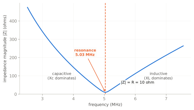
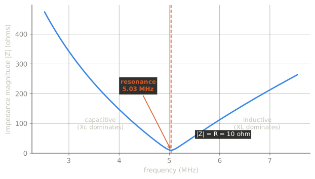
Series and parallel behave oppositely, and Extra tests both properties of both.
| Series resonance | Parallel resonance | |
|---|---|---|
| Impedance magnitude | approximately the circuit resistance | approximately the circuit resistance |
| Input current | maximum | minimum |
| Circulating current in L and C | — | maximum |
| Voltage and current phase | in phase | in phase |
Both read “approximately equal to circuit resistance” — the pool asks each separately and they have the same answer, because at resonance the reactances cancel and only resistance remains. The value of that resistance differs enormously between the two cases (small in series, large in parallel), but the statement is the same.
The parallel pair is the counterintuitive one:
What is the magnitude of the current at the input of a parallel RLC circuit at resonance?
Minimum.
What is the magnitude of the circulating current within the components of a parallel LC circuit at resonance?
It is at a maximum.
Large current sloshes back and forth between L and C, while almost none flows in or out. The tank circuit is storing energy and exchanging it internally; the source only has to make up the losses.
And at resonance, voltage and current are in phase — the definition of a purely resistive impedance.
Q
Q is the ratio of energy stored to energy lost per cycle, and it has two formulas that are reciprocals of each other. Getting them the wrong way round is the most common error in this subelement.
How is the Q of an RLC parallel resonant circuit calculated?
Resistance divided by the reactance of either the inductance or capacitance
Either — because at resonance X_L = X_C, so it does not matter which you use.
A memory hook: in a series circuit the resistance is in the way, so more R means lower Q — R in the denominator. In a parallel circuit the resistance is a leakage path across the tank, so more R means higher Q — R in the numerator.
Half-power bandwidth
7.1 MHz, Q of 150: 7.1×10⁶ / 150 = 47.3 kHz
3.7 MHz, Q of 118: 3.7×10⁶ / 118 = 31.4 kHz
Half-power means the −3 dB points, the same convention as every filter specification.
What raising Q costs you
Two consequences, both asked, and both worth understanding rather than memorising.
What is the result of increasing the Q of an impedance-matching circuit?
Matching bandwidth is decreased.
Directly from BW = f₀/Q. A high-Q matching network matches beautifully at one frequency and poorly a little either side — which is exactly the mobile-antenna bandwidth problem from the General track, seen from the circuit side.
What is an effect of increasing Q in a series resonant circuit?
Internal voltages increase.
The voltage across the inductor and across the capacitor is Q times the applied voltage. They are equal and opposite, so they cancel in the total — but each is individually real. A Q of 100 with 100 V applied means 10 kV across the coil.
What can cause the voltage across reactances in a series RLC circuit to be higher than the voltage applied to the entire circuit?
Resonance
This is why antenna tuner capacitors arc, why mobile loading coils flash over, and why a high-Q circuit is a high-voltage circuit whatever the supply says.
Check yourself
- L = 20 µH, C = 100 pF, R = 15 Ω. Resonant frequency?
- A parallel resonant circuit has R = 5 kΩ and X = 50 Ω. What is Q, and the bandwidth at 14 MHz?
- Why does a high-Q antenna tuner need bigger capacitor spacing than a low-Q one?
Answers
- √(20×10⁻⁶ × 100×10⁻¹²) = 4.472×10⁻⁸; f₀ = 3.56 MHz. R is irrelevant.
- Parallel, so Q = R/X = 5000/50 = 100. BW = 14×10⁶ / 100 = 140 kHz.
- Internal voltages are Q times the applied voltage, so a high-Q network develops much higher voltages across its reactances — and arcs at spacings a low-Q one tolerates.