What an op-amp is
What is an operational amplifier?
A high-gain, direct-coupled differential amplifier with very high input impedance and very low output impedance.
Four properties, and the pool asks two of them separately:
- Very high input impedance — it draws essentially no current from what drives it.
- Very low output impedance — its output holds its voltage under load.
- Very high open-loop gain — typically 100,000 or more.
- Direct-coupled — it amplifies down to DC.
The high gain is not there to be used directly. It is there so that negative feedback can set the gain precisely with two resistors, and the op-amp’s own variation stops mattering.
The inverting amplifier
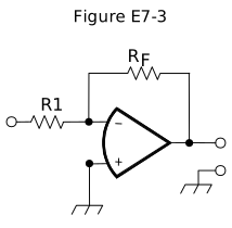
Gain is the ratio of two resistors and nothing else. The op-amp’s own gain cancels out, which is the whole reason for feedback.
Four worked answers, exactly as the pool asks them:
| R1 | R_F | Gain |
|---|---|---|
| 10 Ω | 470 Ω | 470/10 = 47 |
| 1800 Ω | 68 kΩ | 68000/1800 = 38 |
| 3300 Ω | 47 kΩ | 47000/3300 = 14 |
| 1000 Ω | 10 kΩ | 10 — and with 0.23 V in, out is −2.3 V |
The minus sign is the inversion. Questions asking for “absolute voltage gain” want the magnitude; the one supplying an input voltage wants the sign.
Non-ideal behaviour
An ideal op-amp is a useful fiction. Three departures from it are asked.
How does the gain of an ideal operational amplifier vary with frequency?
It does not vary with frequency.
Ideally flat. Really, not:
What is the gain-bandwidth of an operational amplifier?
The frequency at which the open-loop gain of the amplifier equals one.
Gain-bandwidth product is roughly constant: an op-amp with a 1 MHz GBW gives a gain of 10 up to 100 kHz, or a gain of 100 up to 10 kHz. Gain and bandwidth trade directly, which is why an audio op-amp is useless at RF.
What is meant by the term “op-amp input offset voltage”?
The differential input voltage needed to bring the open loop output voltage to zero.
Real inputs are not perfectly matched, so a small differential voltage is needed to balance them. Multiplied by the closed-loop gain, offset appears as a DC error at the output — which matters in a DC-coupled instrumentation circuit and not at all in an audio one.
Adding a feedback capacitor
What is the frequency response of the circuit in E7-3 if a capacitor is added across the feedback resistor?
Low-pass filter.
The capacitor’s reactance falls as frequency rises, so the effective feedback impedance falls, so the gain falls — a low-pass response. It is the standard way to roll off an op-amp stage above the frequencies you care about, and it also tames the stability problem below.
Stability
How can unwanted ringing and audio instability be prevented in an op-amp audio filter?
Restrict both gain and Q
An active filter with high gain and high Q is close to oscillating: the ringing you hear on a transient is that near-oscillation. Both parameters have to be kept modest, and if you need a sharp response, cascade several gentle stages rather than pushing one hard.
This is the same trade as the antenna Q lesson — high Q, narrow response, and ringing on anything that changes quickly.
Check yourself
- R1 = 2.2 kΩ, R_F = 100 kΩ. Absolute gain?
- An op-amp has a 4 MHz gain-bandwidth product. What is its usable bandwidth at a gain of 20?
- Your active audio filter rings on speech transients. What do you adjust?
Answers
- 100000 / 2200 = 45.5.
- 4 MHz / 20 = 200 kHz.
- Reduce gain and Q. If you need the sharpness, cascade gentler stages.