Reading figure E7-1
Three questions point at one schematic, and they are really asking whether you can recognise a standard biasing arrangement.
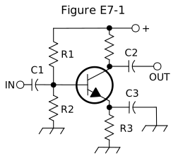
What type of amplifier circuit is shown in Figure E7-1?
Common emitter.
In Figure E7-1, what is the purpose of R1 and R2?
Voltage divider bias
In Figure E7-1, what is the purpose of R3?
Self bias
The pattern to recognise, because it appears in almost every discrete transistor stage ever built:
- Two resistors from supply to base to ground form a voltage divider that sets the base voltage.
- A resistor in the emitter leg provides self bias — sometimes called emitter degeneration. If collector current rises, the emitter voltage rises, which reduces base-emitter voltage, which reduces the current. Negative feedback that stabilises the operating point against temperature and device variation.
- The output taken from the collector, with the emitter common to input and output, makes it a common emitter stage.
The three configurations
| Configuration | Input impedance | Phase | Typical use |
|---|---|---|---|
| Common emitter | moderate | inverting | voltage gain |
| Emitter follower (common collector) | high | in phase | impedance buffering |
| Grounded grid (common base/gate) | low | in phase | RF power amplifier input |
What is characteristic of an emitter follower (or common collector) amplifier?
Input and output signals in-phase
It has no voltage gain — the output follows the input — and its value is impedance transformation: high input impedance, low output impedance. A buffer.
What is a characteristic of a grounded-grid amplifier?
Low input impedance.
Which is why a grounded-grid tube amplifier can be driven directly by a 50-ohm exciter with little matching, and why it is the standard HF amplifier topology.
Operating point
What is the operating point of a Class A common emitter amplifier?
Approximately halfway between saturation and cutoff.
Halfway, so the signal can swing equally in both directions without clipping either. That is what makes Class A linear, and biasing it there is what the divider and emitter resistor exist to do.
Classes, continued
The General track covered A, B, and C. Extra adds two more.
For what portion of the signal cycle does each active element in a push-pull, Class AB amplifier conduct?
More than 180 degrees but less than 360 degrees
Class AB sits between B (exactly 180°) and A (360°). In a push-pull pair each device handles one half-cycle with a little overlap, and the overlap is the point: it eliminates the crossover distortion that pure Class B suffers where the two devices hand over.
Class AB push-pull is the standard HF linear amplifier.
What is a Class D amplifier?
An amplifier that uses switching technology to achieve high efficiency.
Why are switching amplifiers more efficient than linear amplifiers?
The switching device is at saturation or cutoff most of the time.
The efficiency argument is exact. A device dissipates power only when it has both voltage across it and current through it. At saturation the voltage is near zero; at cutoff the current is near zero. Spend almost all the time at one extreme or the other and dissipation approaches zero.
What circuit is required at the output of an RF switching amplifier?
A filter to remove harmonic content.
The price. A switching waveform is full of harmonics — that is what a square wave is — so a Class D or E RF amplifier is not usable without a strong output filter. The filter is not an accessory; it is part of the amplifier.
Which of the following is the likely result of using a Class C amplifier to amplify a single-sideband phone signal?
Signal distortion and excessive bandwidth
The General point restated with its consequence: non-linear amplification of an amplitude-varying signal produces distortion, and distortion produces bandwidth.
Stopping oscillation
What can be done to prevent unwanted oscillations in an RF power amplifier?
Install parasitic suppressors and/or neutralize the stage.
Two distinct problems with two distinct cures:
- Neutralisation cancels feedback at the operating frequency, via deliberate opposite-phase feedback. That is the General answer.
- Parasitic suppressors — typically a small resistor and inductor in parallel in the plate or drain lead — kill oscillation at VHF, far above the operating frequency, where stray inductance and capacitance form their own resonant circuit that the designer never intended.
An amplifier can be perfectly neutralised at 14 MHz and still oscillate at 100 MHz. The two fixes address different frequencies and neither substitutes for the other.
Check yourself
- You see two resistors forming a divider to the base and one in the emitter. What is each doing?
- Why does a Class D RF amplifier need an output filter?
- Your amplifier is neutralised and still self-oscillates. What next?
Answers
- The divider sets the base bias voltage; the emitter resistor provides self bias — negative feedback that stabilises the operating point.
- Its output is a switching waveform, rich in harmonics. The filter removes them and is part of the amplifier rather than an accessory.
- Parasitic suppressors. Neutralisation addresses the operating frequency; parasitic oscillation happens at VHF, from stray reactances.